LoRa Note 1 - experiment setup
Hardware
- Gateway: USRP X310 or B210, etc.
- LoRa node: 1) LoRa Shield 915 MHz; 2) Arduino uno R3;
- Antenna: directional and omnidirectional antennas (915MHz) or RFID antennas; For example, S9028PCR96RTN;
- Adapter/Convertor: RP-TNC female plug to SMA male plug, or SMA Male to SMA Female Coax Adapter, or Maxmoral N Type Male to SMA Male Convertor, etc. These are used for conecting antennas to LoRa devices, which are decided by the type of antennas.
- Other: Laptop or desktop; Ethernet cable connecting USRP and the laptop; A-Male to B-Male cable connecting LoRa node and desktop;
Software
- Labview: LabView Professional Development System 2018 SP1 or newer version; Signal receiving, processing, real-time demo at USRP.
- Matlab: Signal processing and analysis;
- Ardunio: Arduino-1.8.3 or newer version; For signal transmitting and receiving at LoRa node;
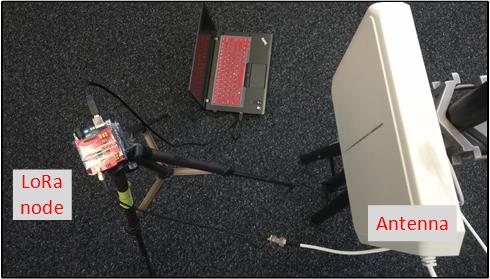
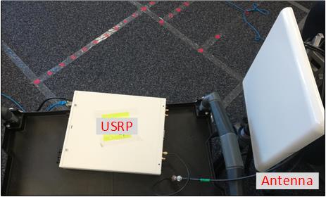
LoRa Experiment Setup -- Example for 1TX&1RX
-
Device
- 1 directional antenna connected to USRP X310 as RX;
-
1 directional antenna connected to LoRa node as TX;
-
1 desktop connected to USRP via the Ethernet cable;
-
TX Setting
-
Ardunio code download
-
Code for LoRa signal transmission
- File path: Arduino-Profile-Examples / libraries / Dragino / examples / LoRa / LoRa_Simple_Client_Arduino / LoRa_Simple_Client_Arduino.ino
-
Modifying code
- Step 1: change frequency from 868MHz to 915MHz, i.e., float frequency = 915.0;
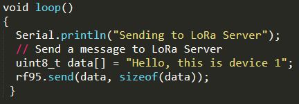
- Step 2: change Function loop() to
- Step 3: connect LoRa node to the desktop and then select the serial port at the Ardunio platform;
- Step 4: upload the code to LoRa node, refer to the video (time: 2:30~3:10 min)
-
Powering the LoRa node
- use large battery or just connect it to the desktop;
-
RX Setting
-
Desktop
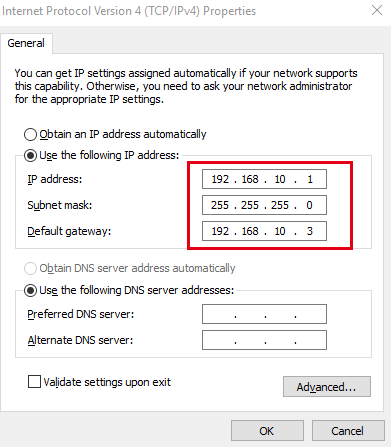
- Change the IP address of desktop to 192.168.10.1;
-
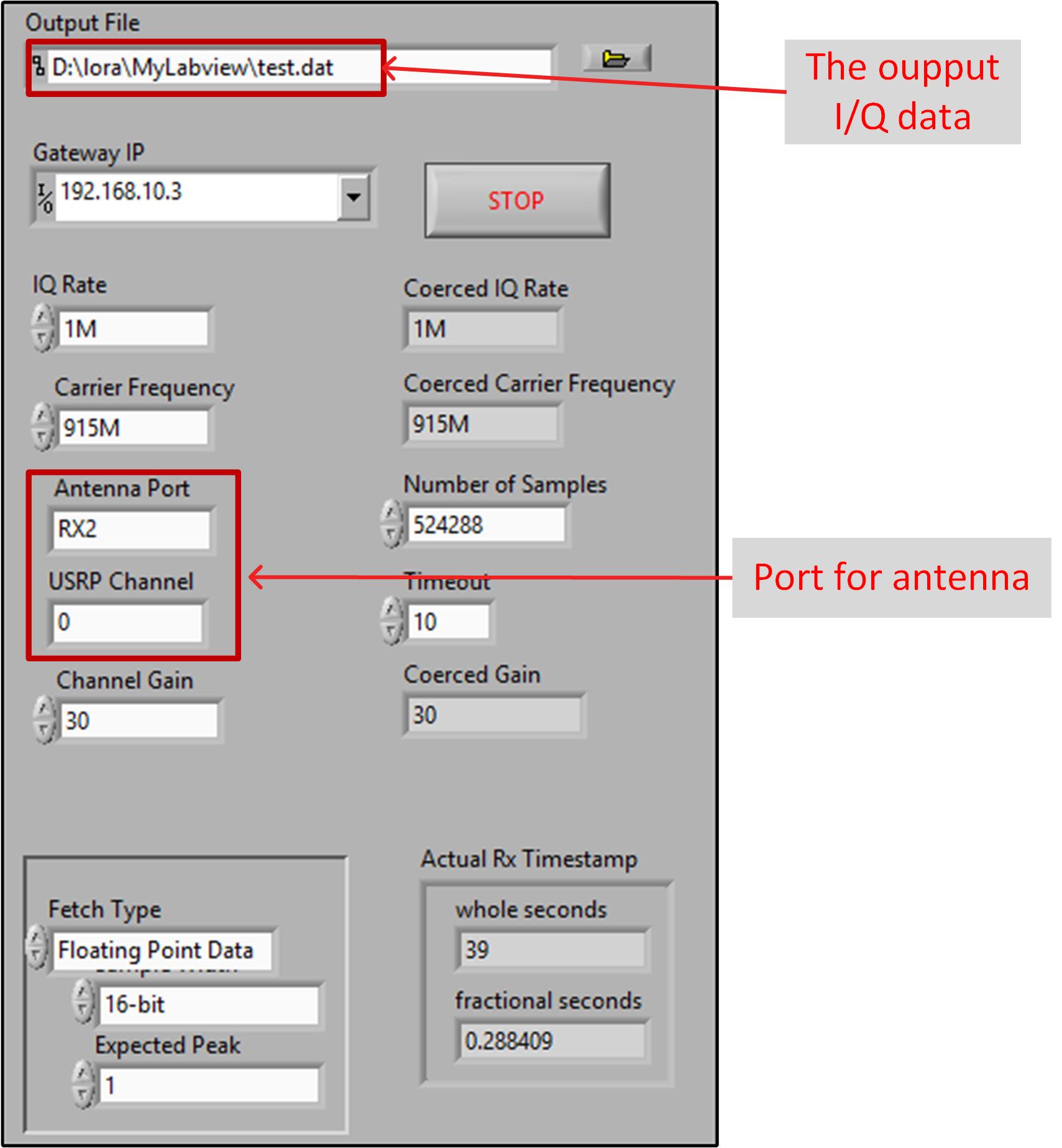
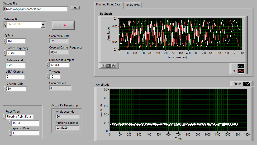
Labview parameter setting
-
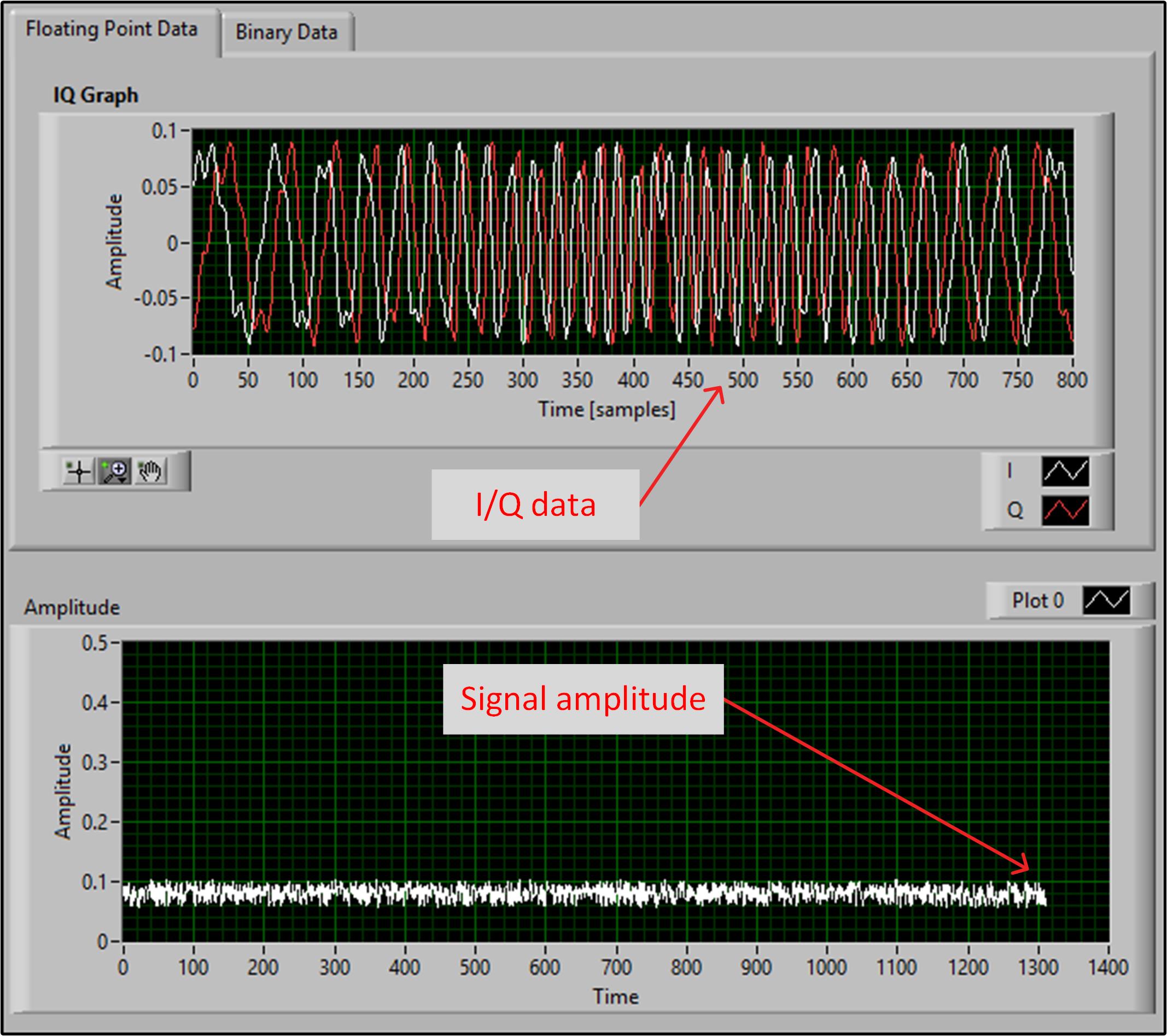
Receiving data
-
Demo
-
Labview file download
-
Matlab code for chirp analysis


